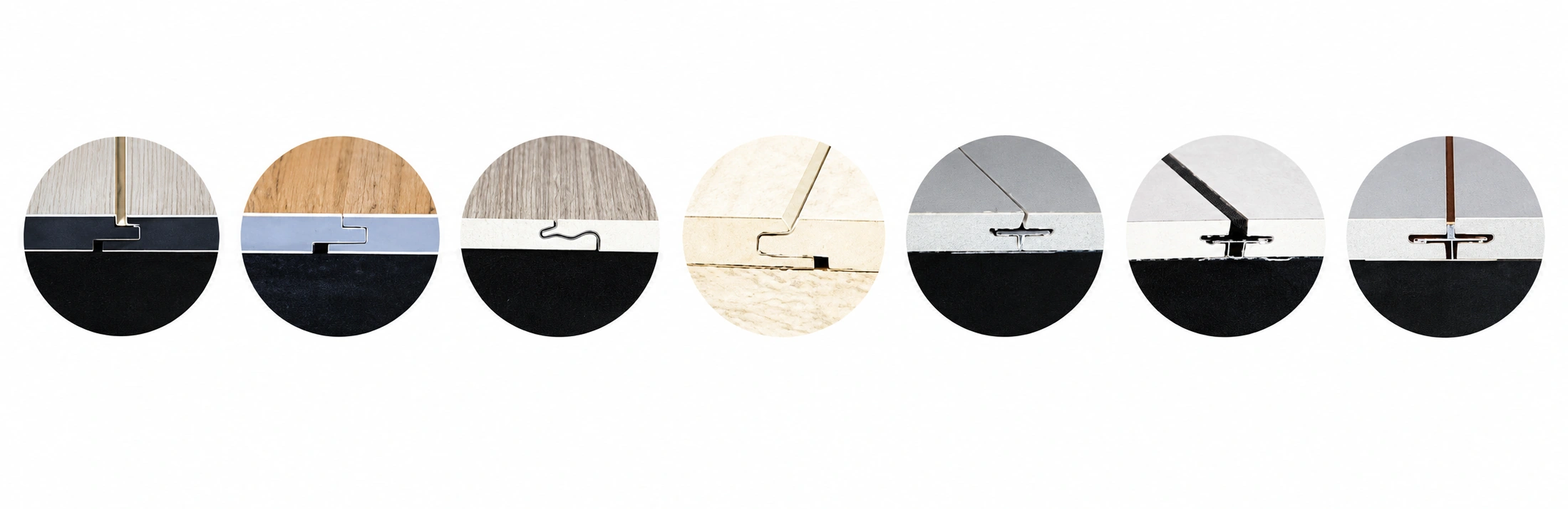
Explore panel edges, finishing elements and clip-on ceiling connections.
PRODUCT / READING GUIDE
First choose the edge. Then the connector.
Factory-grooved, trim-free joints and double-female grooves with separate profiles are different connection systems. Compare the edge geometry before selecting a connector.
01
U joint02
Flat / straight groove03
Seamless locking groove04
V joint05
Double-female groove · I profile06
Double-female groove · twin-rib internal I profile07
Double-female groove · 土-shaped profile
Restored illustrations. Use the approved section drawing for installation.
01
Four trim-free groove appearances
U joint; flat / straight groove; seamless locking groove; V joint. These four factory-grooved connections require no separate joint trim. That statement concerns the junction: it does not mean the board needs no wall fixing.
The remaining drawings are labelled double-female + I profile, double-female + twin-rib internal I profile, and double-female + 土-shaped profile. Their different connector sections must not be collapsed into one “locking” system.
Accessory 24925 explicitly names a double-groove 土 connector; 24926 names a double-groove U-joint strip and 24927 a straight-joint strip. Select the connector together with the board thickness and approved section; these fittings are not universal.
6 cm hook-on skirting: 24932–24934, length 2.5 m, three named colours; matching-height accessory entries 24935–24939 cover left / right ends, straight connection and internal / external corners. The separate 8 cm group is 24940 (2.5 m) and accessories 24941–24945. Match height and engagement geometry to the approved section.
Bring the board code, thickness, edge photo, connector code and finish reference into the same enquiry. Use the product-specific installation specification for adhesive, fixing spacing, movement allowance and load requirements.
Compare shaped panel edges and separate metal trims. These connection details complement the product-specific installation design.
U-shaped joint
The recessed joint remains visible between panel faces.
V-shaped joint
Two bevelled edges meet to form a V-shaped surface line.
Recessed trim
A separate dark metal profile occupies the recessed junction.
I-profile connector
The connector receives adjacent board edges; its face defines the joint line.
Flat joint
The photograph shows aligned face planes and a fine joint.
Locking connection
The two sample boards expose complementary shaped locking edges.
No numerical gap, adhesive, fixing interval or snap-in force is given in these photographs. They are decorative-panel details and are not re-labelled as SPC details. Use the approved construction drawing for installation.
DETAILS / ACCESSORY SCHEDULE
Resolve joints, corners and ends.
Browse 62 accessories for joints, corners, ends and skirting. Use the model number to request a matching sample.
Model
Product name
English description
24901
10金属T型线
10 metal T trim
24902
20阳角线-同色覆膜
20 external-corner trim — matching laminate
24903
10金属装饰线(扣条)
10 metal decorative clip strip
24904
20金属装饰线(扣条)
20 metal decorative clip strip
24905
30金属装饰线(扣条)
30 metal decorative clip strip
24906
05厚0.5金属工字线
05 / 0.5 metal I trim
24907
05厚0.5金属收口线
05 / 0.5 metal end trim
24908
05厚0.88金属凹型线
05 / 0.88 recessed metal trim
24909
05厚金属阳角线
05 metal external corner
24910
05厚金属阴角线
05 metal internal corner
24911
05厚高档金属阳角线
05 premium metal external corner
24912
08厚0.82金属工字线-同色覆膜
08 / 0.82 metal I trim — matching laminate
24913
08厚0.52金属收口线
08 / 0.52 metal end trim
24914
08厚0.89金属凹型线
08 / 0.89 recessed metal trim
24915
08厚金属阳角线
08 metal external corner
24916
08厚金属阴角线
08 metal internal corner
24917
08厚金属顶角线
08 metal top-corner trim
24918
08厚土字型金属线条
08 土-shaped metal trim
24919
08厚高档金属阳角线
08 premium metal external corner
24920
09厚0.35金属工字线
09 / 0.35 metal I trim
24921
09厚0.8金属工字线
09 / 0.8 metal I trim
24922
09厚金属收口线
09 metal end trim
24923
09厚0.9金属凹型线
09 / 0.9 recessed metal trim
24924
09厚金属阴角线
09 metal internal corner
24925
双母槽-土型金属线条
Double-groove 土-shaped connector
24926
双母槽-U型缝金属条
Double-groove U-joint metal strip
24927
双母槽-直缝金属条
Double-groove straight-joint metal strip
24928
08厚0.38金属工字线-同色覆膜
08 / 0.38 metal I trim — matching laminate
24929
08厚0.52金属收口线-同色覆膜
08 / 0.52 metal end trim — matching laminate
24930
08厚金属大阳角-同色覆膜
08 large metal external corner — matching laminate
24931
08厚金属尖阳角-同色覆膜
08 pointed metal external corner — matching laminate
24932
6公分挂钩踢脚线-肌肤黑-2.5米
6 cm hook-on skirting — skin black — 2.5 m
24933
6公分挂钩踢脚线-星空灰-2.5米
6 cm hook-on skirting — star grey — 2.5 m
24934
6公分挂钩踢脚线-高光白-2.5米
6 cm hook-on skirting — gloss white — 2.5 m
24935
6公分左堵头 配件
6 cm left end cap
24936
6公分右堵头 配件
6 cm right end cap
24937
6公分中接 配件
6 cm straight connector
24938
6公分阴角 配件
6 cm internal corner
24939
6公分阳角 配件
6 cm external corner
24940
8公分挂钩踢脚线-肌肤黑-2.5米
8 cm hook-on skirting — skin black — 2.5 m
24941
8公分左堵头 踢脚线配件
8 cm left end cap
24942
8公分右堵头 踢脚线配件
8 cm right end cap
24943
8公分中接 踢脚线配件
8 cm straight connector
24944
8公分阴脚 踢脚线配件
8 cm internal-corner accessory
24945
8公分阳脚 踢脚线配件
8 cm external-corner accessory
24946
100顶角线
100 top-corner trim
24947
100踢脚线
100 skirting
24948
60*20收口线
60 × 20 end trim
24949
80装饰线
80 decorative trim
24950
60装饰线
60 decorative trim
24951
25角线
25 angle trim
24952
20阴角线
20 internal-corner trim
24953
35*45边框
35 × 45 frame
24954
36装饰线
36 decorative trim
24955
30实心装饰线
30 solid decorative trim
24956
40实心装饰线
40 solid decorative trim
24957
50实心装饰线
50 solid decorative trim
24958
60实心装饰线
60 solid decorative trim
24959
66实心装饰线
66 solid decorative trim
24960
80实心踢脚线
80 solid skirting
24961
60实心收口线
60 solid end trim
24962
双眼皮顶角线
Double-step top-corner trim
Select accessories by model, section and board thickness. Confirm the matching connection and fixing method; model designations are not dimensional specifications.
SPC / DETAIL PREPARATION
Separate surface engraving from installation.
Select the SPC surface layout and construction, then coordinate the installation detail for the project.
What can now be specified
Request the named finish, the plain or coded engraving pattern, the panel width and length, and a matching physical sample. For engraved panels specify 600 mm width and length below 3000 mm.
Use a product-specific approved detail for substrate preparation, cutting, adhesive or mechanical fixing, movement gaps, corners and wet-area sealing. A shower application image is not approval of a waterproof wall assembly.
Separated board edges reveal the groove and projecting faces. Use the product-specific installation detail to match the connector and fixing.
Rounded section with a perforated flange
A broad curved face, internal cavity and perforated side flange define this section.
Two faces meeting at a corner
The section shows two angled decorative faces, internal webs and return edges. Board engagement, angle tolerance and compatible thickness need the corresponding dimensioned drawing.
A return lip and an open channel
A narrow curved lip meets a wider open channel, creating a different return geometry from the broad corner section.
Match four things before ordering
Specify the panel model and thickness, connector section, junction location and approved fixing detail together. Similar-looking profiles are not interchangeable.
Six documented edge appearances, kept distinct from the fixing specification.
DECORATIVE-PANEL EDGE DETAIL
Double groove + connector
Both grooved panel edges receive a separate connector. The connector remains visible as a defined line between panels.
Related drawing: 8 mm double-groove decorative panel; 610.5 mm overall width.
These are joint and edge photographs, not a complete installation manual. The substrate, adhesive, anchorage, movement allowance, site conditions and inspections need an approved product-specific installation design.
02 / FINISHING ELEMENTS
Resolve the junction.
35–45 edge frame
45 × 35 · t 3 mm
25–25 corner trim
25 × 25 · t 2.5 mm
60–30 closing trim
60 × 30 mm
80 solid skirting
80 × 12 mm
Dimensions describe the illustrated sections. Confirm panel compatibility and fixing separately.
03 / CLIP-ON CEILING
A connection you can understand.
Three operations connect suspension, carrier and clip-on profiles.
Component diagram, not to scale or for installation.
The diagram shows rods suspended from the ceiling structure, supporting the carrier below. It begins with levelling the suspension. The anchorage design, load capacity and rod spacing require project approval.
Use the approved project details and load design for suspension height, spacing and fixings.
SURFACE / COMPOSITION
Plan the pattern before the panel.
The decorative design, the panel structure and the installation joint answer different questions. Compare them together without treating a surface appearance as a performance specification.
Follow the sequence
Read the complete wall, not one small sample. Establish panel order and grain direction around doors, corners and focal points.
Create a centre
A mirrored composition makes a feature of the meeting line. Review the paired design before choosing the wall centre and edge cuts.
Think in two directions
For multi-row layouts, consider horizontal and vertical continuity together. Keep decorative alignment separate from the fixing and joint detail.
Layout illustrations, not an installation drawing or a finish availability list. Choose the final composition with the selected panel and physical sample.